




1. Project Overview
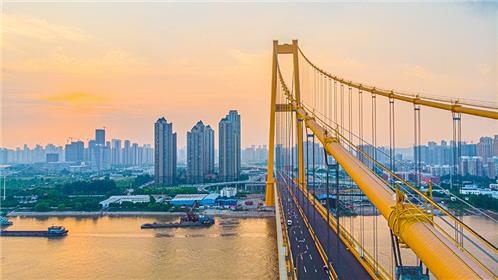
The Yangsi Port Expressway, as one of the "three rings and thirteen shots", consists of four sections: the Sixin section, the Yangsi Port Yangtze River Bridge crossing section, and the Qingling section. The Qingling section of Yangsi Port Expressway (from Batan Interchange to Dingziqiao Road) starts from Batan Interchange on Baishazhou Avenue in the west and ends at Dingziqiao Road in the east, with a total length of 4.459 kilometers and a road red line width of 60-70 meters. The entire line is constructed in the form of elevated and ground auxiliary roads, with a total length of 508 meters for the railway cable-stayed bridge, starting from K2+738.98 and ending at K3+246.98. The main bridge adopts a (40+88+252+88+40) m twin tower cable-stayed bridge (center pile number K2+992.98), with a two-way eight lane bridge deck (both sides of the collision avoidance zone also serve as pedestrian walkways), and a design speed of 60 kilometers per hour. The main bridge is located in the middle and front section of the Qingling section, crossing the Jiang'an Rolling Stock Depot lead line, the Beijing Guangzhou Railway up line, the Wunan marshalling yard, the welded rail base, the Beijing Guangzhou Railway down line, the Wushi Intercity Yuhua Connection Line, and the Wuchang Shouyi College from west to east. The geographical location of this project is shown in the following figure:
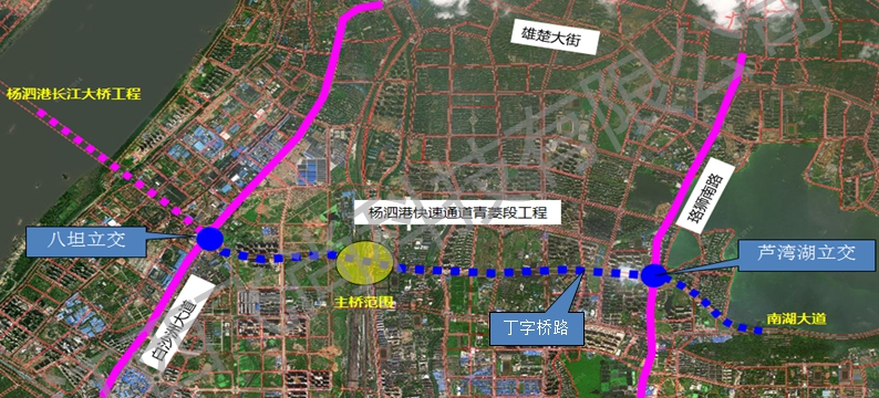
Project Geographic Location Map
According to regional geological data, the geological structure of the proposed project site is stable. Although there are structural faults passing through along the line, they belong to early faults and no Holocene active faults have been found. The structural stability in the site area is good. The site is distributed with some special rock and soil or adverse geological processes such as fill soil, soft soil, expansive soil, karst, etc.
II. Monitoring Purpose
By dynamically tracking and inspecting the bridge structure in use and monitoring its environmental conditions, existing defects and quality degradation of the structure can be identified in a timely manner, and its possible development trend under the environmental conditions and potential threats to the safe operation of the structure can be evaluated and analyzed. This provides a scientific basis for maintenance needs and decisions, in order to achieve better maintenance results with limited maintenance funds and ensure the safe operation of the structure.
(2) Set multi-level safety warning thresholds for bridge structures. Evaluate the health condition, structural safety and reliability of the bridge structure, and then provide feedback to the bridgeThe operator provides level warning information. When the performance of the bridge changes beyond the warning threshold under complex operational loads, timely warning forecasts can be given to remind managers to conduct necessary detailed inspections and maintenance of the bridge structure in a timely manner.
(3) Verify the effectiveness of various design assumptions and parameters during the design and construction phases, and conduct post validation of the design and construction. It is necessary to study the changes in mechanical and physical properties of bridges under long-term operation, in order to accumulate valuable data and experience for health monitoring and safety assessment of large bridges.
In summary, by establishing an advanced and practical health monitoring system for the Yangsi Port Qingling section cable-stayed bridge, real-time monitoring of the bridge's operational status can be achieved, and real-time safety alarms can be issued for the bridge; Reasonably allocate bridge maintenance resources, provide scientific and technological basis for reducing bridge operation and maintenance costs, and ensure that the development of bridge inspection and maintenance strategies is targeted, timely, and efficient.
III. Monitoring Content

System Overall Framework Diagram
List of Measurement Point Layout for the Main Bridge of Qingling Cable stayed Bridge
| Monitoring Type | Monitoring items | Sensor type | Quantity | Monitoring section | |
| Bridge site environmental monitoring | Wind speed and direction | Wind speed and direction indicator | 2 | Tower top, main span mid span | |
| Atmospheric temperature and humidity | Temperature and humidity meter | 2 | Tower top, main span mid span | ||
| Local temperature and humidity of the structure | Temperature and humidity meter | 4 | Anchor zone of bridge tower cable, mid span of secondary side span, quarter point of main span | ||
| External effect monitoring | Vehicle information | Vehicle overweight (including snapshot) | Dynamic weighing system (four lanes) | 2 | Two side beam end approach bridge |
| Structuretemperature | Bridge tower temperatureConcrete temperature sensor | 12 | Bridge tower cantilever beam section, lower tower column | ||
| Main beam temperature | Steel temperature sensor | 20 | Secondary edge spans mid span, main span mid span | ||
| Structural safety performance monitoring | Structural strain | Bridge tower strainConcrete strain sensor | 20 | Bridge tower cantilever beam section, middle tower column and lower tower column junction, tower bottom | |
| Main beam strain | Steel strain sensor | 38 | Auxiliary pier support point, secondary side mid span, bridge tower support point, main span mid span | ||
| Bearing platform strain | Concrete strain sensor | 16 | Upper pedestal | ||
| Deformation monitoring | Main tower space deformation | GNSS | 3 | Tower top, base point | |
| Main beam deflection | Deflectometer | 18 | Mid span of side span, mid span of secondary side span, pivot point of bridge tower, quarter point of main span, mid span of main span | ||
| Dynamic deflection | Dynamic deflection sensor | 1 | Main tower lower crossbeam | ||
| Structural vibration | Main beam vibration | Vibration sensor | 16 | Secondary span mid span, main span quarter point, main span mid span | |
| Cable vibration | Cable vibration | Vibration sensor | 8 | Edge Rope | |
| Cable force | Cable force | Cable force sensor | / | Matched with the inclined cable and connected to the monitoring system | |
| Cracks | Sealing hinge crack | Flexible paint sensor | 8 | Tower bottom hinge seal | |
| Bearing working status | Displacement sensor | 8 | Auxiliary pier and main tower support | ||
| Working status of expansion joints | Displacement sensor | 4 | Beam end | ||
| Video monitoring | High definition camera | 6 | Near the beam end approach bridge and the lower crossbeam of the main tower | ||
| Total | 188 | ||||