







Jinjiang Foundation Pit
I. ProjectBackground
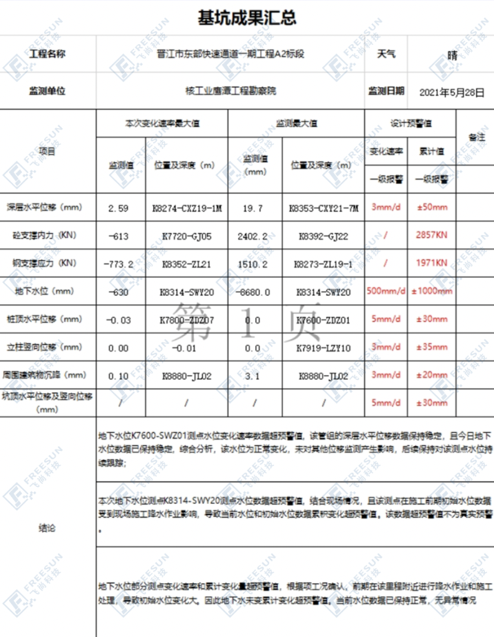
The starting point on the north side of the Jinjiang Eastern Expressway project is about 781m north of Fuxing Road, and the endpoint on the south side is about 488m south of the Weitou branch line. The starting and ending station numbers are K3+140~K8+937, with a total length of about 5.797km. The second section of the Jinjiang Eastern Expressway Phase I project (K7+055~K8+937) is 1.882km long. The scope of this section includes highway engineering (including overall, route, roadbed, pavement, tunnel, route intersection, traffic safety facilities, tunnel attachments, green landscape, other projects, highway related projects, etc.), facilities along the line (including municipal drainage, power pipelines, etc.), and project costs.
The starting mileage of the main tunnel is located at K7+125 and the ending mileage is K8+825, with a total length of 1700m. Among them, K7+125~K7+165 is a single-sided retaining wall section, K7+165~K7+280 is a north open section, K7+280~K8+500 is a tunnel buried section, and K8+500~K8+825 is a south open section. The main line tunnel is designed as first-class highway and urban expressway, with a design speed of 80km/h, and the ramp tunnel is designed as urban trunk road, with a design speed of 40km/h.
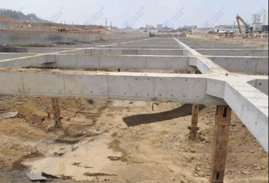
Figure 1-1 Site photo of foundation pit
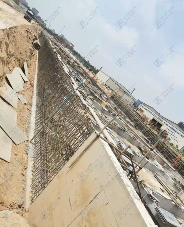
Figure 1-2 Site photo of foundation pit
II. Project Design and Implementation
During the construction of the foundation pit, the excavated soil mainly includes plain fill (1-1), miscellaneous fill (1-3), slope silty clay (5-22), residual sandy cohesive soil layer (6-22, 6-23), locally fully weathered granite (7-10), and sandy strongly weathered granite (7-11) layer; Among them, 1-1 plain fill and 1-3 mixed fill are both soft soils with characteristics such as easy softening and collapse when exposed to water; Residual sandy cohesive soil (6-22), residual sandy cohesive soil (6-23), 7-10 fully weathered granite (7-10), and sandy strongly weathered granite (7-11) layers are all special rock and soil with adverse characteristics of easy softening and disintegration when soaked in water.
This project adopts two monitoring methods: manual and automated.
Manual monitoring: Monitor the slope section of the Jinjiang East Expressway, and manual monitoring mainly includes slope horizontal and vertical displacement, as well as groundwater level monitoring.
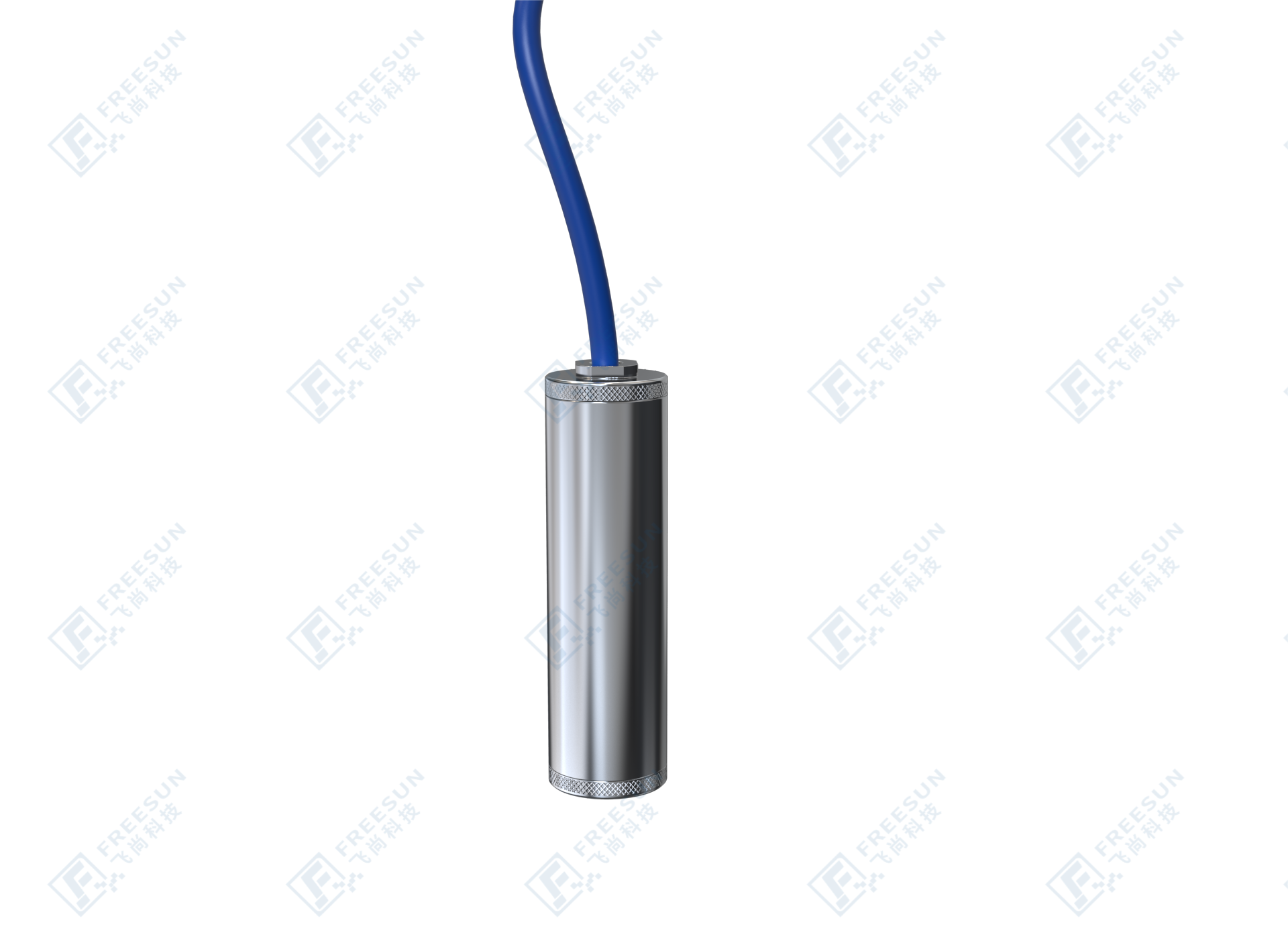
Automated monitoring: deep horizontal displacement of pile body, horizontal and vertical displacement of pile top, axial force of steel support, internal force of reinforced concrete support, settlement of support columns, groundwater level outside the foundation pit, settlement of surrounding (pit top) surface, and settlement of surrounding buildings.
Table 2.1 Monitoring Content and Measurement Point Layout
Serial number | Location of measurement points arrangement | Principles for Layout of Measurement Points | Number of measuring points (pieces) | |
1 | Deep horizontal displacement | Internal part of pile (wall) | Distance of 40m | 48 |
2 | Horizontal and vertical displacement of pile top | Upper end of drilled pile | Distance of 40m | 48 |
3 | Steel support axial force | Supporting end | Take a monitoring section for every 5 reinforced concrete supports, with one axial force meter for each steel support on each monitoring section | 48 |
4 | Internal force of reinforced concrete support | Reinforced concrete support inside | Take a monitoring section every 5 reinforced concrete supports, with two monitoring points for each reinforced concrete support | 96 |
5 | Support column settlement | Column end | Not less than 2% of the total number of columns and not less than 3 columns | 48 |
6 | Pit top water level and vertical displacement | Surrounding the foundation pit | Distance of 40m | 48 |
7 | Groundwater level monitoring | Groundwater level outside the foundation pit | Hole spacing 40m | 48 |
8 | Settlement of surrounding buildings | Corner points and column foundations of buildings | Monitor buildings within 1-3 times the excavation depth of the foundation pit | 4 |
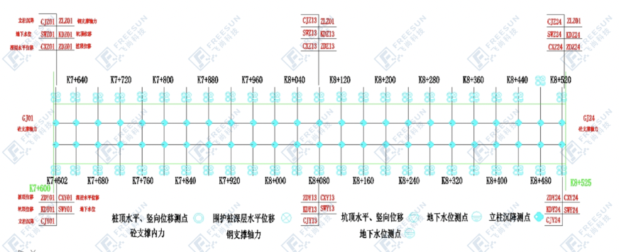
Figure 2-1 Overall layout of measuring points
III. Function Implementation
Data Statistics
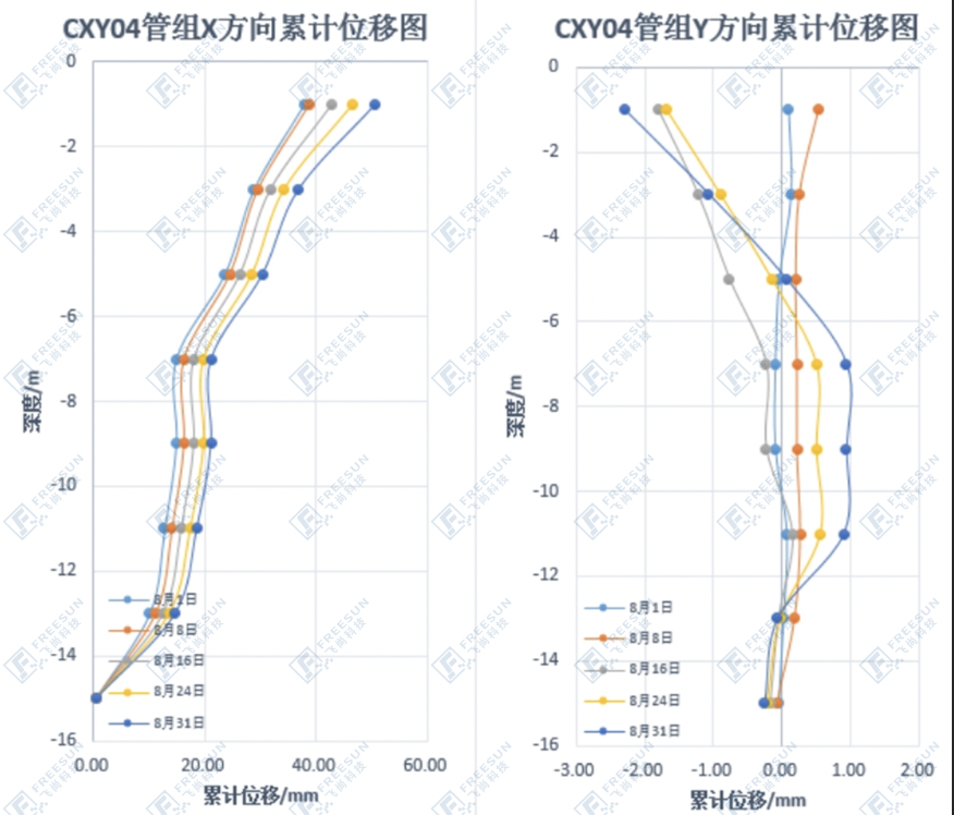
Figure 3-1 Cumulative displacement trend chart of K7680-CXY04 pipe group (left X, right Y)
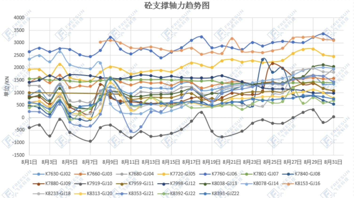
Figure 3-2 Trend chart of axial force of reinforced concrete support